Early on in the process, pi-top’s Mechanical Design Engineer, Chris started making plans for our robot but everything changed in January after a brief discussion with our CTO Ryan, which led to Robo-Top becoming something of a pi-top Frankenstein’s Monster.
As I’m not massively technically-minded, Chris is going to take over the blog post from here and fill you all in with the journey from Brian’s Max Robot to pi-top’s monster.
Space claim analysis
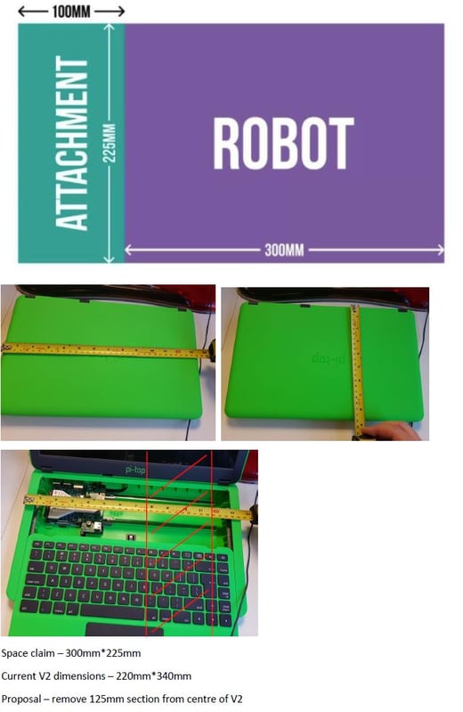
After deciding to mount a pi-top on the robot, the first we had to do was a space claim analysis. We had to compare the size of a pi-top to the robot space claim specified in the PiWars' rules.
Our pi-top is 340mm wide and 220mm deep. The PiWars space claim is 225mm wide and 300mm deep. In order to fit out pi-top in the space claim, we decided to trim a 125mm section from the centre.
Modification of pi-top
Before we can modify the pi-top, we had to remove all the parts we didn’t need.
[gallery ids="1459,1458" type="rectangular"]
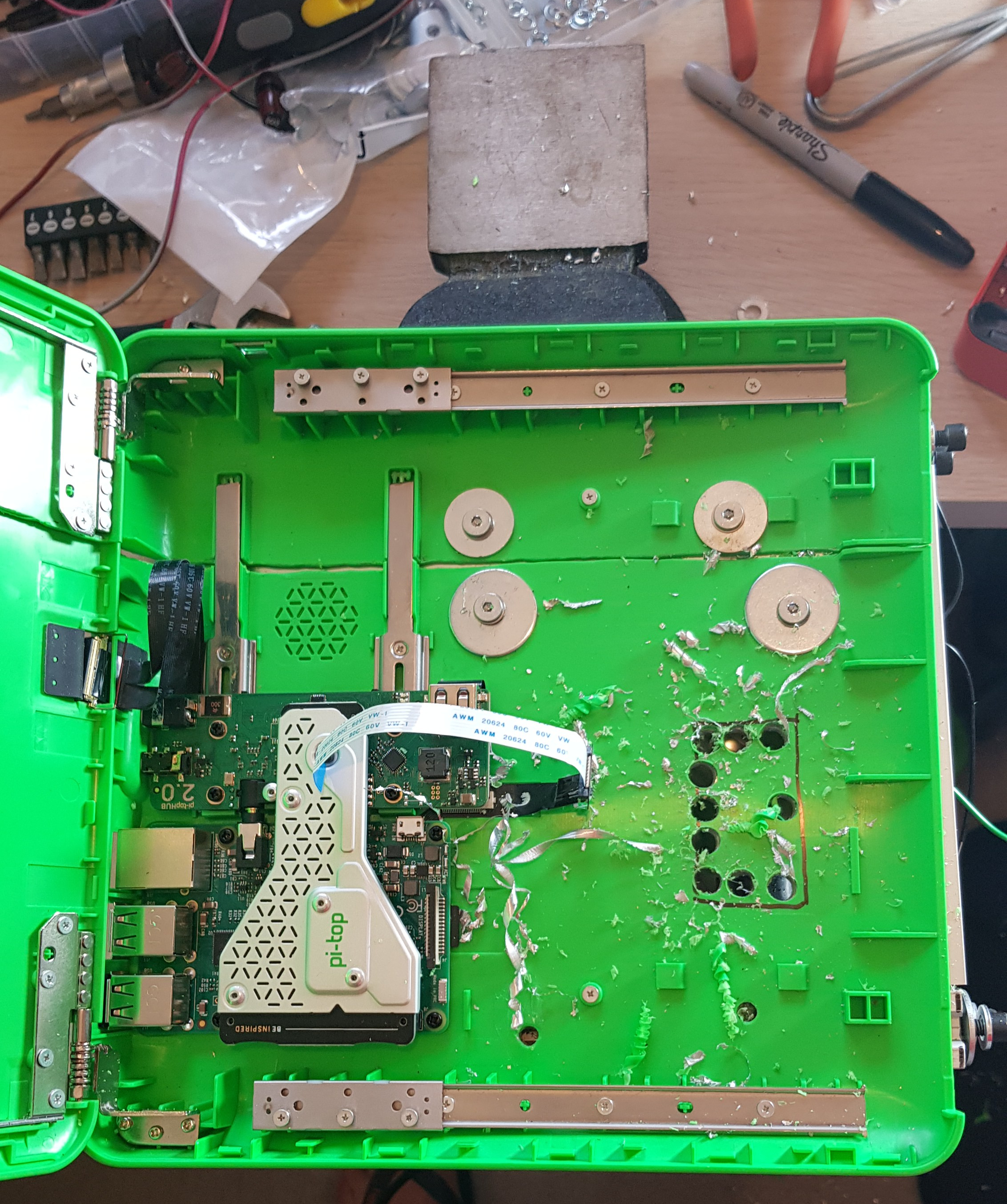
To allow the pi-top to still function after modification, we had to consider carefully where to cut so as not to hinder electrical or mechanical functionality. We measured where we wanted to cut and fired up the dremel! The initial cut was straight through, then once the unit was in two pieces, it was easier for us to precisely cut to the required dimensions.
[gallery ids="1460,1461" type="square" columns="2"]
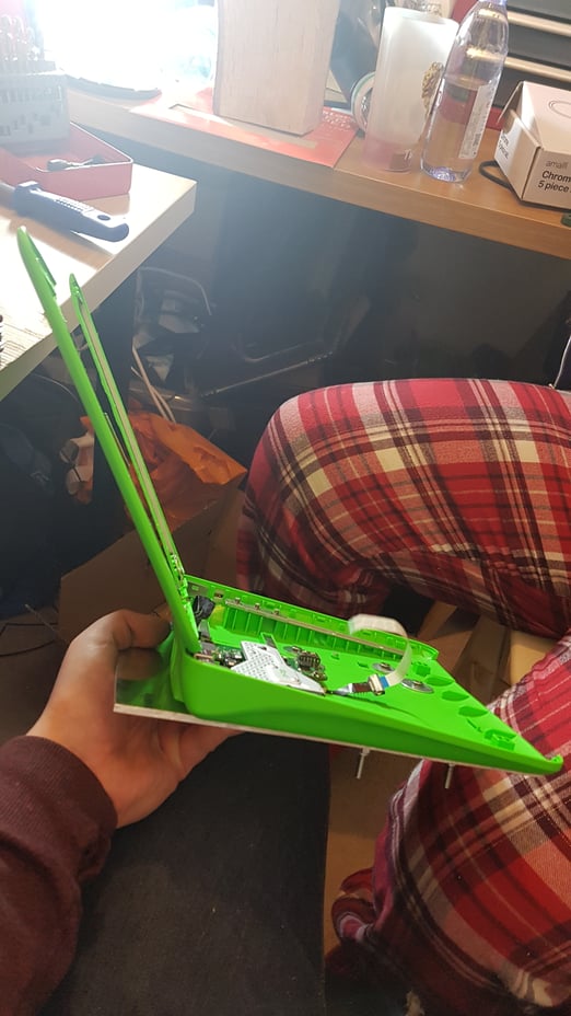
Now we have trimmed the pi-top to our desired size, the next job is to re-attach the remains back together, ensuring the mag rails on the LSH lined up in their remaining chassis slots on the RHS. We decided the easiest way to do this would be to mount it onto an Aluminium base plate - this would provide strong structural rigidity as well giving us a good platform to build from.
 pi-top re-attached and mounted on Aluminium plate
Undercarriage manufacture
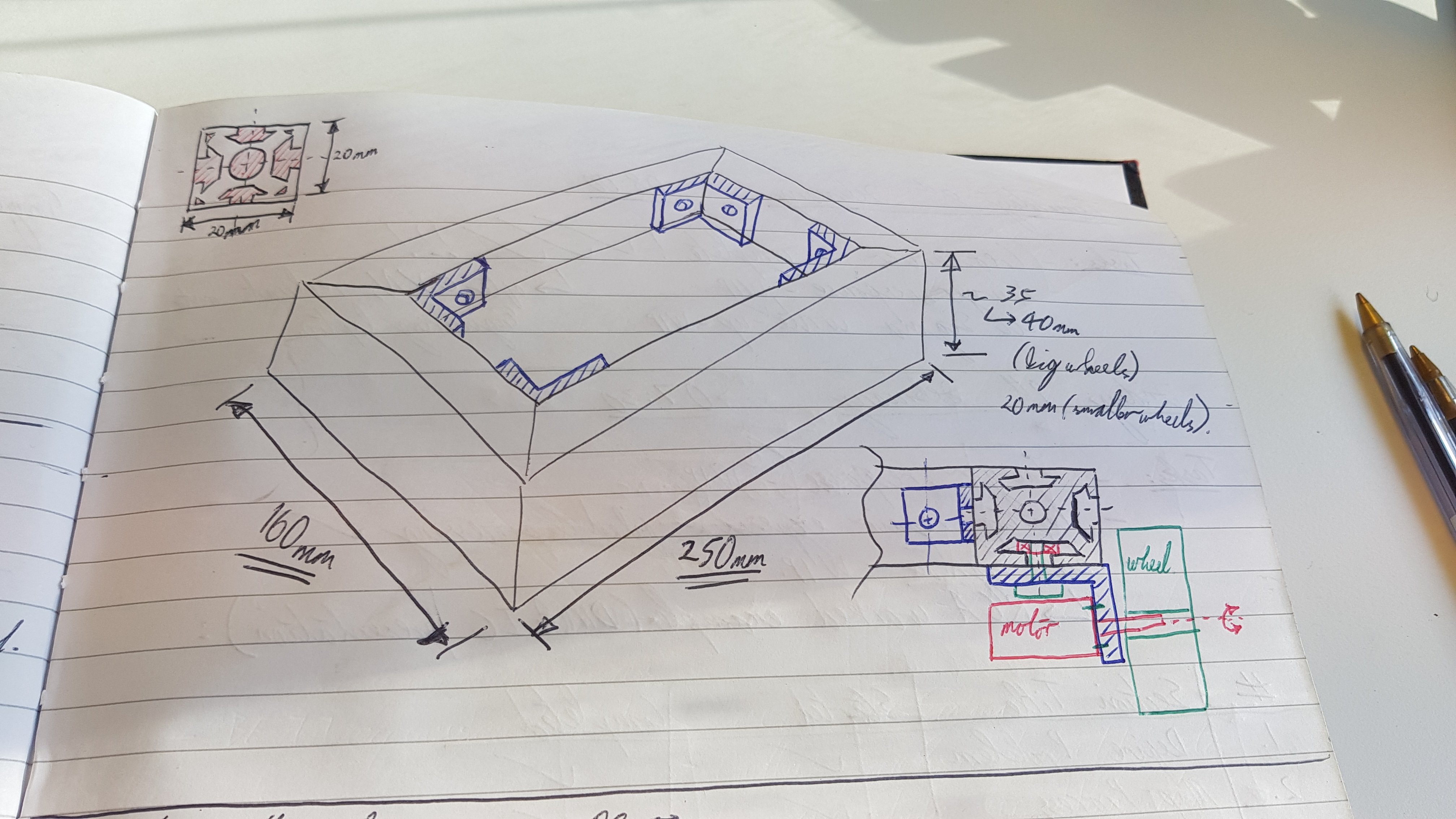
We decided to use to aluminium t-slot extrusion to fabricate an undercarriage to sit beneath the aluminium base plate. This would give us a very flexible setup allowing wheel motors, sensor PCBs and PiWars challenge specific hardware to be mounted at any location around the robot - ideal for the development phase, as we don’t currently know the exact positions we want to mount things.
 Concept sketch of robot undercarriage
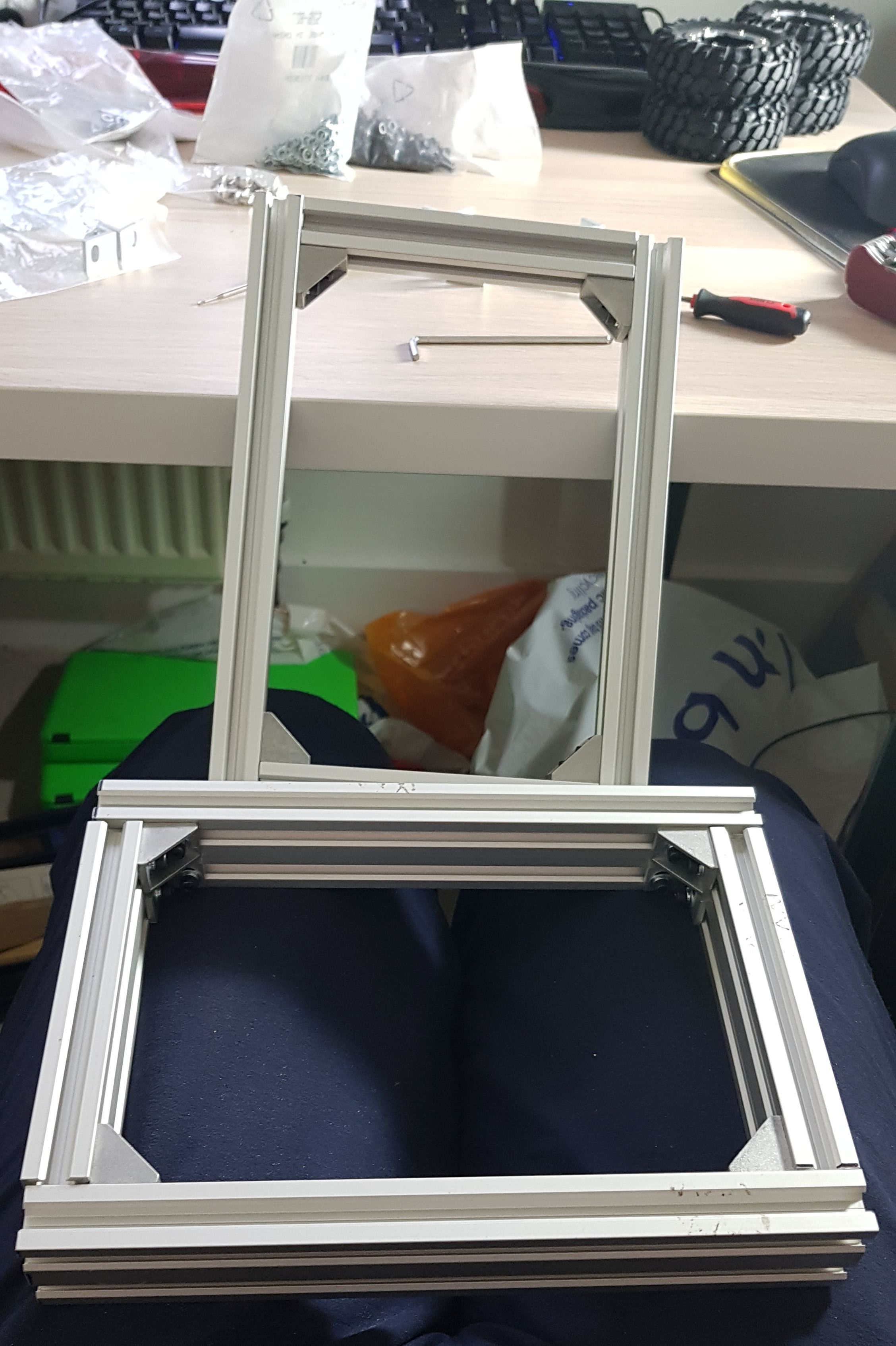 Robot undercarriage
Motor bracket design
The brackets we were using to fix the wheel motors onto the chassis had a couple of issues that made them a bit fiddly to use - the screw location for fixing them to the chassis was underneath the motor. This meant if we wanted to swap out the brackets, the motor had to be taken off to gain access to the attachment screws - not ideal if we needed to quickly swap out brackets in the competition! We thought we could design some better ones.
We created a CAD model of the motor bracket design using SolidWorks and then 3D printed some.
[gallery ids="1465,1466" type="rectangular"]
The motor bracket designs were checked with the motors and once we had confirmed all the holes lined up correctly, we mounted the motors onto the undercarriage.
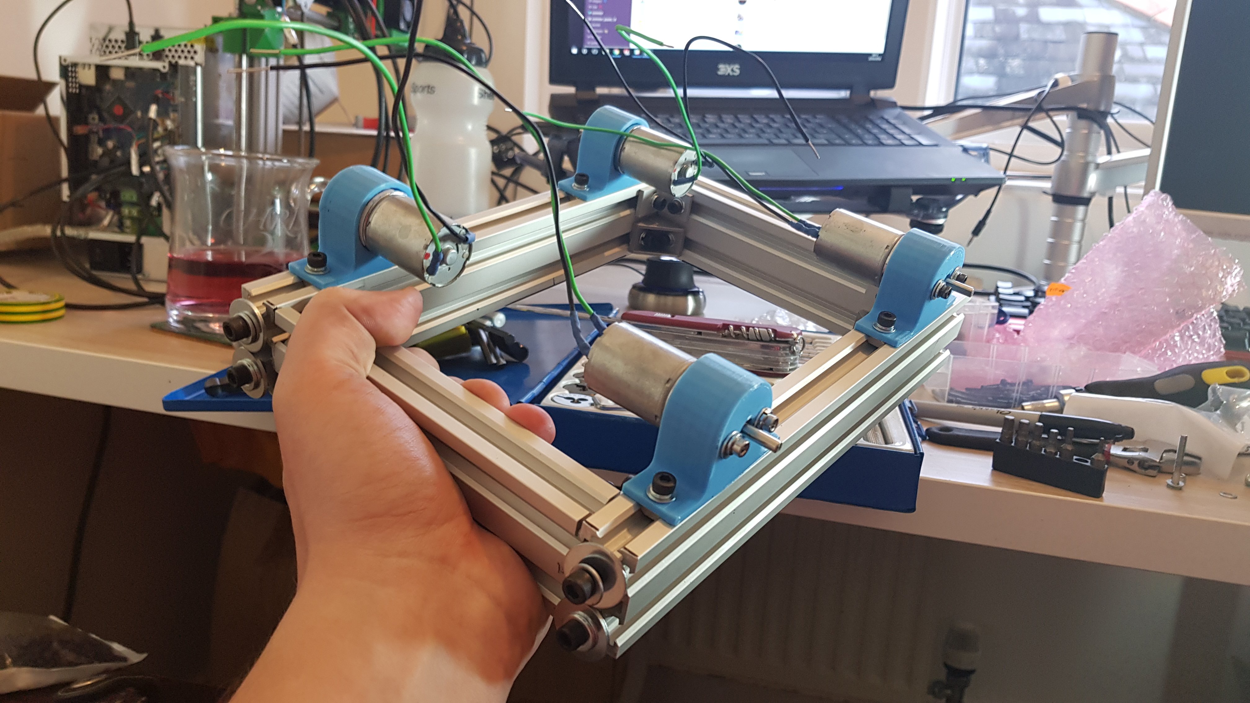
As can be seen in the picture above, with the new motor design the robot mounting screws are much easier to access. This allows us to remove the motor and bracket as one assembly, allowing for faster motor interchange at competition time!
Peripheral sensors
We decided to make four break-out sensor circuit boards to fit around the peripherals of the robot. They would each be fitted with a camera and distance sensor, allowing us to more easily control the position of the robot on the PiWars challenge courses.
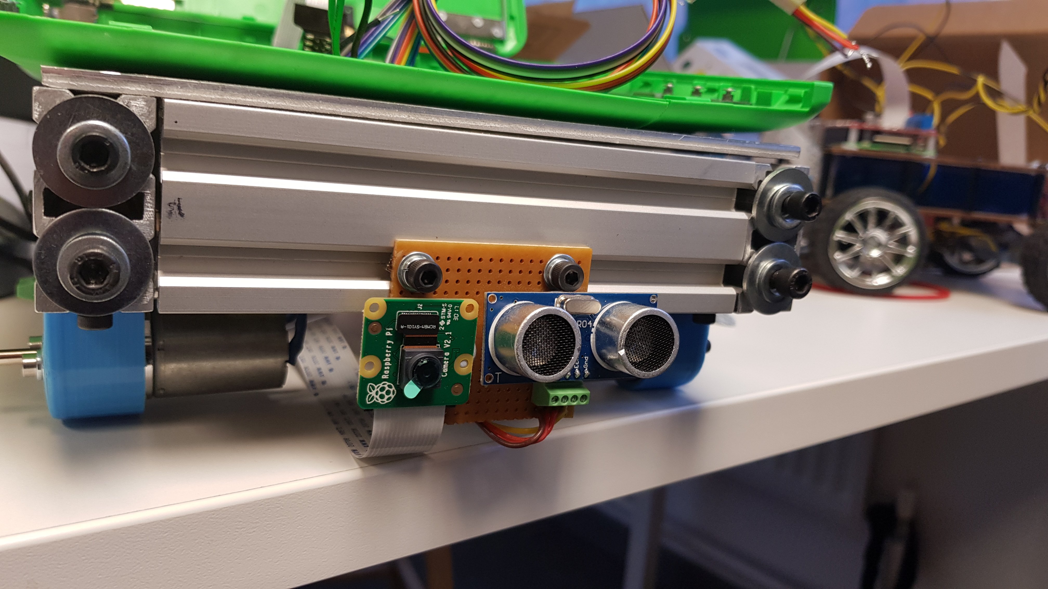
Electronic pass-thrus & wiring looms
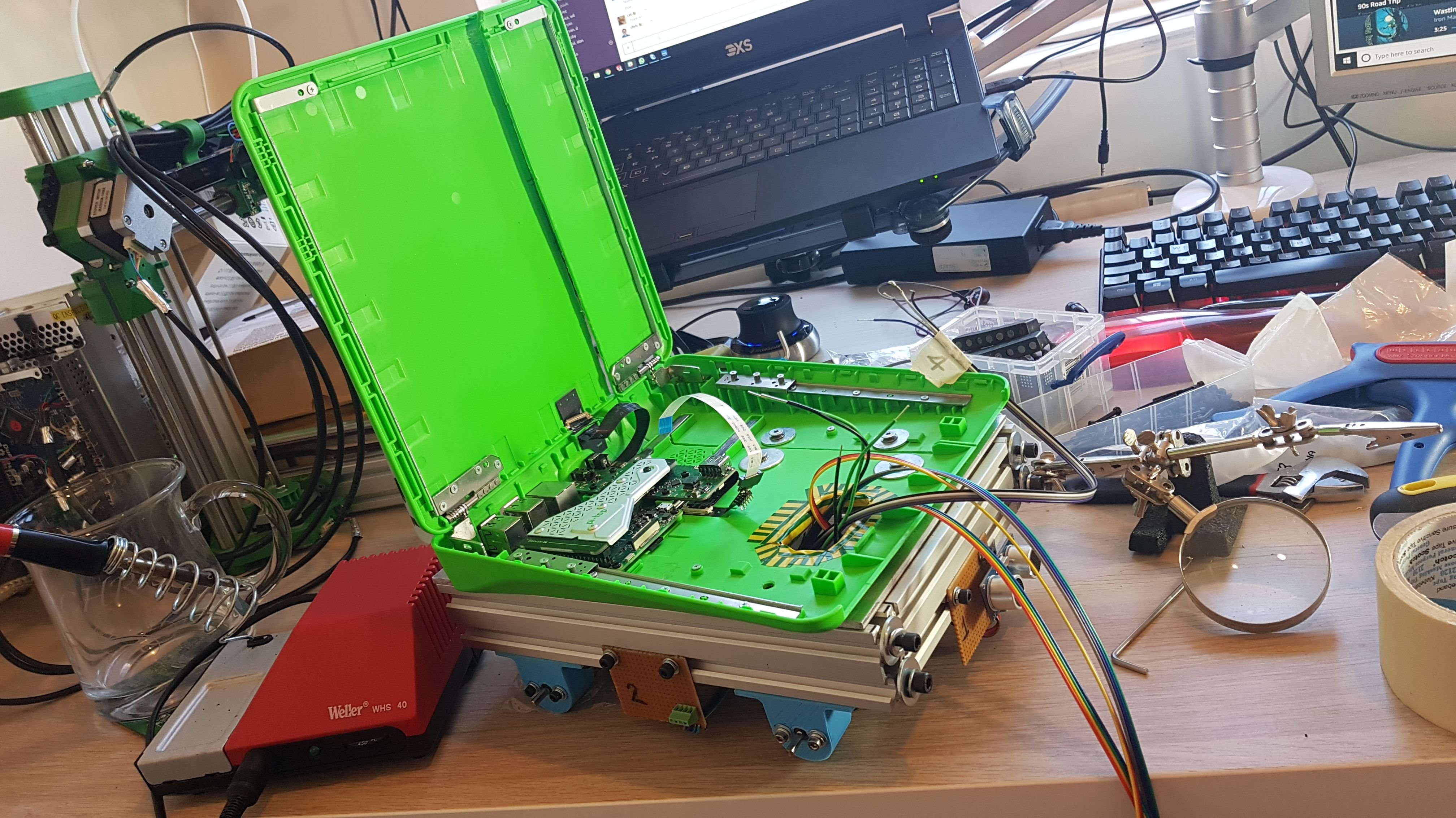
We needed to create an electronics pass-thru on the robot to allow wires from the undercarriage up through to the laptop chassis and pi controller. We decided to drill a big hole straight through the middle!
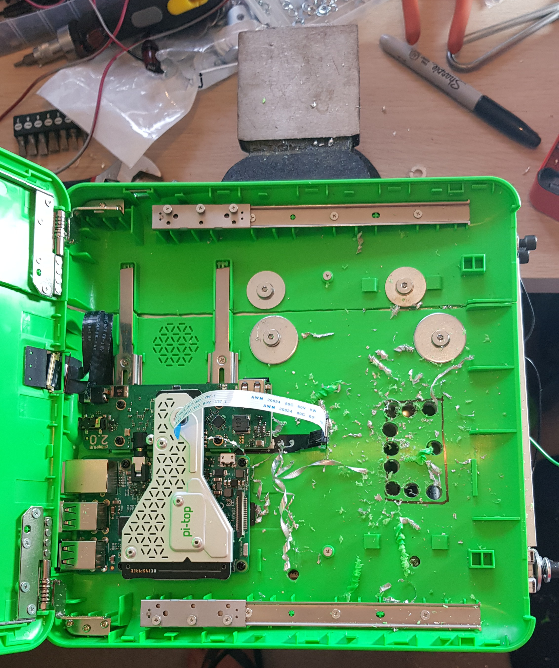
Once the pass-thru hole had been drilled and deburred, we decided to tape the periphery to help prevent damage to cable looms.
[gallery ids="1471,1472" type="rectangular"]
Now we were ready to run the cable looms from each of the sensor break-out boards and the motors from the undercarriage up to the pi-top chassis.
Further Work
Thus ends the blog for part 1 of the mechanical build. We still have the following on the agenda for future mechanical build blogs:
- Wiring loom connectors - quick interchange to be competition ready
- Battery and other electrical component mounting
- LCD screen sub-system design
- Wheel optimisation
Until then, please enjoy the Rocky-esque montage of the engineering build!
[wpvideo Bw1gL2Op]
